So you think you might have bricked your router, and are cringing at the idea of another $210 for a new one? I’m guessing this has something to do with DD-WRT flash to stock or upgrade? If that’s the case, just drop the entire idea of DD-WRT; Kong’s image completely cripples this router’s speed performance, and pfsense is a far superior alternative. Let’s get to it!
PREREQUISITE (READ 1ST BEFORE CONTINUING)
Going forward with this guide it is Assumed That you have disconnected everything from your router!! The only connection being a Single Patch cable from Port 1 to your PC, Nothing Else plugged into the Router! This guide is for Windows users, Sorry but I do not know anything in terms of Apple, and most linux Users can easily follow along and find the equivalent.
Getting our Diagnosis
The first thing we need to do is what is known as a 30/30/30 reset, do not proceed without having attempted this first, not that it’s likely to resolve the issue, but it will put the router in the state we want it for moving forward.
1. 30/30/30 Reset
- With the Router Plugged in, Push & hold the reset button for 30 seconds.
- With the Button still being pressed & Held, unplug the Router for 30 Seconds.
- Still holding the reset button down, no plug the Router back in & hold for another 30 seconds. (The button should be held for 90 Seconds Total)
2. Determine Possibility of Communication
- Open the Command Prompt Window (Windows Button, Type: “CMD”)
- Type:
ping -t 192.168.1.1 - Plug power into Router
- watch the Responses on the screen for a minute or two.
If your Output looks Similar to this:
Reply from 192.168.1.1: bytes=32 time<1ms TTL=100
Reply from 192.168.1.1: bytes=32 time<1ms TTL=100
Reply from 192.168.1.1: bytes=32 time<1ms TTL=100
Reply from 192.168.1.1: bytes=32 time<1ms TTL=100
Reply from 192.168.1.1: bytes=32 time<1ms TTL=64
Reply from 192.168.1.1: bytes=32 time<1ms TTL=64
Reply from 192.168.1.1: bytes=32 time<1ms TTL=64
You are in Great shape!, The bootloader is requesting firmware, then proceeding to communicate with whatever is left of the Router’s OS. Proceed to Step 3.
If your Output looks similar to this:
Reply from 192.168.1.1: bytes=32 time<1ms TTL=100
Reply from 192.168.1.1: bytes=32 time<1ms TTL=100
Reply from 192.168.1.1: bytes=32 time<1ms TTL=100
Reply from 192.168.1.1: bytes=32 time<1ms TTL=100
Reply from 192.168.1.1: bytes=32 time<1ms TTL=100
Reply from 192.168.1.1: bytes=32 time<1ms TTL=100
Reply from 192.168.1.1: bytes=32 time<1ms TTL=100
As before we are in good shape. We are communicating with the router and the bootloader (CFE) is advising us it is in need of Firmware ( TTL=100). Go ahead and proceed to Step 3.
If your Output looks Similar to this:
Reply from 192.168.1.1: bytes=32 time<1ms TTL=100
Reply from 192.168.1.1: bytes=32 time<1ms TTL=100
Reply from 192.168.1.1: bytes=32 time<1ms TTL=100
Request timed out.
Request timed out.
Request timed out.
Request timed out.
Your bootloader is requesting Firmware initially for a few seconds before losing connection, this is due to the boot wait being enabled. After the router boots, it loses it’s ability to communicate. On a positive note you have a window of opportunity for communication, but unfortunately not much. Proceed to Step 4.
If your Output looks Similar to this:
Request timed out.
Request timed out.
Request timed out.
Request timed out.
Request timed out.
Request timed out.
Request timed out.
Try changing the ping command to: ping -t 192.168.1.2 and cycle through 3, 4, 5, 6, 7, 8 (eg 192.168.1.3) if the output remains the same for every IP you are “Officially” bricked, you have no communication with the router and will require a Serial Transfer/jtag. Proceed to Step 5.
Note on LED’s: I did not specifically cover LED’s as there is no outlined document explicitly defining LED patterns and their relation to the current state of the router. The only thing known is that the LED’s on your Router will not be acting normally, including solid Orange LED, All LED’s solid on ports not even plugged in, No wifi LED present etc.
We will be attempting a few different methods of flashing the firmware to the Router, starting with Netgear’s suggested method that usually works in cases with a failed or corrupted Update.
3. TFTP Transfer
Download the Official Firmware from here (For R7000P Routers only!)
Download Tftpd64 client from here
We have 2 options for doing the TFTP transfer including Netgear’s suggested method using a utility called “Tftpd64” or we can use Windows built in TFTP client which many users swear has a higher success rate. I will go ahead and cover both with the initial setup being the same.
Changing Network Adapter Settings:
- Right click Windows Start, Select Network Connections.
- Click on “Ethernet” on the right, then click “Change Adapter Options“
- Right click on your “Ethernet ” connection, and select “Properties“
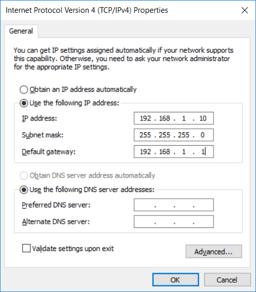
- Select “Internet Protocol Version 4 (TCP/IPv4)” and click “OK”
- Make the following Changes:
- Open Command Prompt and type:
ping -t 192.168.1.1 - Move the Command window while pinging to the side but in view
- Open ttpd64, switch to “Tftp Client” and change the following:
- “Server Interfaces” The current lan Adapter connected to your router.
- Host: 192.168.1.1
- Port: 69
- Local File: Select your Netgear Official .chk Firmware file.
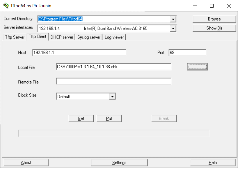
Now with everything setup we want to wait before clicking put.
Power off your router for 10 Seconds, Power back on, when you first see the following line in the command line:
Reply from 192.168.1.1: bytes=32 time<1ms TTL=100
That is when you “press put“
Note: you may need to try a few times to get the timing just right, you are wanting to send the firmware the instant the router requests it with the TTL=100.
If you are successful you should get a popup stating “0 block retransmitted”

Don’t touch anything just yet, wait 5-10 minutes for the router to finish loading the firmware into memory, The Power & Wifi LED’s will turn solid, login to the router perform a Factory reset from the Configuration Menu and you are done.
Don’t forget to change your Static IP address settings back to default, or you will not have internet.
Window TFTP Client Transfer Alternative
If you Skipped the 1st part, make sure you go back and update the Internet Protocol Version 4 (TCP/IPv4) settings before proceeding.
- Control Panel > Programs > Turn Windows Features On or Off > Enable TFTP Client

- Open Command Prompt and type:
ping -t 192.168.1.1 - Move the Command window while pinging to the side but in view.
- Open another Command Prompt and Type:
cd desktop - Move the firmware file to desktop if it isn’t already there.
- In the CMD window Type:
tftp -i 192.168.1.1 put firmareName.chk - Do Not press Enter just yet
- Power off the Router for 10 sec
- Power back on the router, holding the Reset Button down for 10 seconds, the continue watching the ping attempts.
when you first see the following line in the command line:
Reply from 192.168.1.1: bytes=32 time<1ms TTL=100
That is when you will “press Enter“
As before the timing is critical with this process, so if you miss it the first time, try doing it again till you get it. When the TFTP client begins transfer the process will continue for several minutes, so ensure you do not power off or reboot the router.
You will see “Transfer Successful” when completed. You should now reboot the router, wait a couple minutes to reload, then login to the interface via web browser.
If you are still unsuccessfully able to get it at this point, and the TFTP transfers are simply not working for you, we have one last route to give a shot before resorting to a Serial Cable, proceed to Step 4.
4. NMRP Flash
Download nmrpflash utility here
- Move the extracted .exe file to the desktop
- Open Command Prompt and type:
ping -t 192.168.1.1 - Move the Command window while pinging to the side but in view.
- Open Command Prompt as Administrator and type:
cd desktop - Type the following:
nmrpflash -L - Identify the correct network controller:
C:\>nmrpflash -L
net0        192.168.1.2         xx:xx:xx:xx:xx:xx     (Ethernet)
net1        0.0.0.0             xx:xx:xx:xx:xx:xx     (Ethernet3)
net2        0.0.0.0             xx:xx:xx:xx:xx:xx     (Wi-Fi)
Now Type: nmrpflash -i net0 -f firmwareName.chkWarning: It will Always Fail the 1st time! press up Key, then Enter (Quickly!!)
After you put the Command in a Second time you should see:
C:\>nmrpflash -i net0 -f R7000P-V1.3.1.64_10.1.36.chk
Advertising NMRP derver on net0 ... \
Received TFTP_UL_REQ while waiting for CONF_REQ!
Received upload request without filename.
Uploading R7000P-V1.3.1.64_10.1.36.chk ...
Received keep-alive request.
Received keep-alive request.
Received keep-alive request.
Received keep-alive request.
Received keep-alive request.
Received keep-alive request.
Received keep-alive request.
Received keep-alive request.
Received keep-alive request.
Received keep-alive request.
Remote finished. Closing connection.
Reboot your device now.
Keep trying till you get it keeping an eye on the pings.
- Once You see the Reboot Text, Wait a few minutes.
- Reboot the device and wait till all LED’s are solid
- Try logging into your device at 192.168.1.1
- Perform a Factory Reset via the GUI interface
- Revert your Lan IP4 Settings back to Automatic
If for whatever reason you are unable to get the transfer to go through, stop take a break for a bit or get some sleep. When you come back to it re check all your connections, settings, and go back over the steps carefully to ensure your not missing anything. If all still fails, unfortunately your last resort is the Serial Cable Transfer. Proceed to Step 5.
5. Serial Flash
Before we can proceed you will need to obtain a USB to TTL Cable More Specifically the FT232RL Type. While you can pick up one with the header already attached, and proceed assuming you “Know the Color Code” of the wires, I highly suggest you purchase something like this that way there is no question.
- Obtain USB to TTL Adapter (FT232RL) Here
- Obtain Netgear Firmware (R7000P) Here
- Install puTTy download here
Preparation
- Disassemble the router (5 Screws on the bottom, under pads/sticker)
- Connect your PC to Router port 1 with Ethernet Cable. (Power Cable Unplugged)
- Connect USB to TTL Adapter, ensure drivers installed
- In Device Manager Identify what “COM” port the adapter is using under Ports (COM & LPT) (eg: COM1, COM2, COM3)
- Open “Internet Protocol Version 4 (TCP/IPv4)” and make the following Changes:

- Connect the Wires from the USB to TTL Adapter to the board
If you purchased the board above, the pins are clearly labeled on the adapter you should have 3 wires connected to GND, TX, RX. (Also flip the Switch to 3.3V) If you are using an different adapter that is Not labeled you will need to decipher the color code of your adapter, more info here.
- Connect the 3 pins accordingly to the pictures below
- Pin 1 VCC 3.3V (Don’t Connect)
- Pin 2 GND
- Pin 3 TX
- Pin 4 RX


- With Serial Adapter Connected lets prepare our input windows
- Open a CMD Prompt window (if you have not configured the Windows TFTP Client refer to previous steps in the guide here)
- Navigate to the directory the firmware is located (eg.
cd C:\) - Type:
tftp -i 192.168.1.1 put firmareName.chkDO NOT PRESS ENTER - Move the Window to the side & open PuTTy
- Select “Serial” in the left hand pane under “Connection”
- Input the Following Settings:
- Serial Line To connect to: Found Earlier
- Speed: 115200
- Data bits: 8
- Stop bits: 1
- Parity: none
- Flow Control: none

- Now click on Session at the top and change Connection type to “Serial”

As for an Explanation too what we are trying to accomplish in these next steps, we are going to try and communicate with the CFE via Serial connection in puTTy, asking for acceptance to transfer a file. Upon acceptance we have a very limited time window of opportunity to respond, in which we need to quickly send that firmware via TFTP. So the proceeding steps need to be done quickly, if you don’t get it the first time, don’t get discouraged, keep trying till you get the timing just right.
- In puTTy click “Open”
- Power on your R7000P Router
You will begin to see similar output on the screen:
CFE for Foxconn Router R7000P Version v1.0.21
Build Datd: Wed Aug 7 19:11:17 CST 2014
Init Arena
Init Devs.
Boot up from NANO flash...
Bootcode Boot partician size = 524288 (0x80000)
DDR Clock : 1350 Mhz
Info: DDR frequency set from clkfreq=1000,*1350*
et0: Broadcom BCM47XX 10/100/1000 Mbps Ethernet Controller 6.37.05.1 (r407936)
CPU type 0x0: 1000MHz
tot mem: 262144 KBytes

Device eth0: hwaddr 04-A1-51-C1-84-42, ipaddr 192.168.1.1, mask 255.255.255.0
          gateway not set, nameserver not set
Startup canceled
If you are not getting any output in the window, try swapping the TX & RX pins, and
start over. Otherwise you have a driver issue.
- As Soon there is output on the screen continuously press
Ctrl^C - If done quickly enough you should be given the following prompt:
Startup Canceled
 ^C
CFE>
- Type:
tftp& press Enter - Verify the following output:
CFE> tftp
Start TFTP Server
Reading : :
- Back to our CMD Prompt press Enter to start TFTP Transfer.
If everything was done properly you should be getting output on both windows referencing the transfer, Don’t touch anything until it is completely finished and you something similar to this:
Transfer Successful: 5439546 bytes in 7 seconds. 7770878 bytes/s
It is important to let the transfer do it’s thing and not touch anything for a few minutes when you are absolutely positive the transfer has been completed. Interrupting the transfer will result in a bad flash, and the process will need to be repeated.
If you are having issues initiating the transfer as mentioned before get both widows prepared, Open the puTTy connection, power on the router and start holding the Ctrl key while pressing C repeatedly till you get the CFE> prompt. The R7000P conveniently has a power button opposed to having to use the power cord making this task a bit easier.
If you just can’t get it to go through, I suggest you look through some of these sources for additional information.
5 Comments
raul · November 17, 2019 at 11:28 pm
thank for your detail information of this manual my router is Back
PhRoZeN CrEw · November 19, 2019 at 11:39 am
Glad to hear it worked out for you! Thanks for the feedback, it’s good to hear from individuals who have benefited from my guides, it gives me motivation to keep writing them 🙂
Mr_Weinstein · April 2, 2020 at 11:00 pm
Thank you very much. Worked first time for me and I have my router back after pulling my hair out
Ivan · March 19, 2023 at 12:26 pm
Thanks for the instruction!
did not help me, even via UART. The red LED blinks constantly – as I understand it is waiting to load and loses the ability to communicate.
I did everything according to the instructions, as described in step 5, but again after data transfer the LED blinks(
PhRoZeN CrEw · April 28, 2023 at 4:04 pm
I’m sorry to hear that. To be honest I have never Had to attempt the JTag previously, Like most other the NMRP Flash was sufficient in getting it back. I did however study the Jtag flash before writing this post and so I know there is allot more info out there on it. I would encourage you to keep looking around for other insights on the issue if you need to get this router back up and running. Though I will say I’m a bit surprised your still using this old Router, I retired mine a couple years ago.